


Search
Intrinsic Safety – what’s it all about?
You visit your local hardware store and buy a light fitting for your home; it’s stylish, convenient, and cheap. Why not do the same at your place of work?
Don’t even think about it!
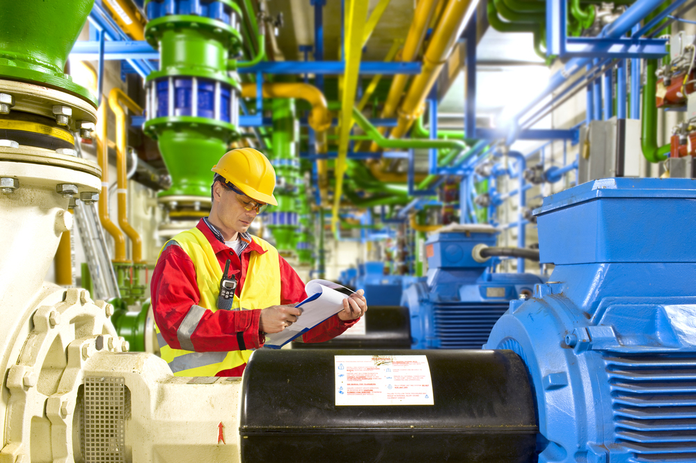
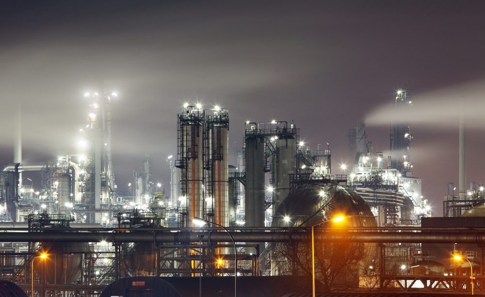
In this Process Safety Dispatch article, we take a look at a rather important measure in preventing explosions on plant where flammable gas, vapor, combustible dust or fibers could be present, in so-called Classified or Hazardous Locations. This month we are demystifying the often-misunderstood concept of Intrinsic Safety (IS).
It must be understood that using ordinary (unrated) electrical equipment and wiring in Hazardous Locations is dangerous and can result in fire or explosion with significant risk to life, the community, plant, and business continuity. Such unrated electrical equipment might produce sparks, arcs or get hot under both normal and abnormal operating conditions or even allow product to enter its enclosures, with potential risk of spark ignition, smoldering combustion, product self-heating, and short circuit. With unrated equipment, no one will have evaluated the potential for these hazards to arise!
Cue ‘explosion proofing’…. and introducing Intrinsic Safety (IS)
To reduce this obvious explosion hazard, you’ll often hear people say, “We must use explosion proof equipment!”, which can be a great idea. Properly designed (and approved) Explosion Proof equipment ensures that arcing or even a gas, vapor, or dust cloud explosion inside the equipment will not be able to ignite any flammable atmosphere surrounding the electrical enclosure.
However, the Explosion proof technique is just one of the methods of protection for equipment used in hazardous locations. Equipment and wiring could be also protected by Intrinsically Safe (IS) design, Purging/Pressurization (preventing flammable atmosphere entering the equipment), or other more exotic methods. In United States, the National Electrical Code (NEC) lists all permitted methods of protection for areas classified under Class/Division system in Article 500.7, and for areas under Class/Zone system in article 506.8 [see table below].
Table 1: US NEC, Article 500.7 Acceptable Equipment Protection Techniques in Hazardous Locations
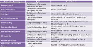
Note: The major difference between the IS and Non-Incendive is that non-incendive circuits are evaluated for ignition capability under normal operating conditions, while intrinsically safe circuits are evaluated under fault conditions.
Intrinsic Safety
So, what is Intrinsic Safety (IS) all about? Intrinsic safety (IS) prevents ignition from occurring by ensuring that the energy transferred to a hazardous area is well below that required to initiate an ignition event. In the context of electrical equipment in hazardous (classified) locations, an Intrinsically Safe circuit is one in which any spark or thermal effect (hot surface) is incapable of causing ignition of a mixture of flammable or combustible material under the conditions for which the equipment is approved, including fault conditions.
The energy levels necessary for operation of many control devices are relatively small, making the IS method of protection possible for a majority of instrumentation systems and signal indicators.
The IS technique can provide advantages, as follows:
- The ‘simple apparatus’[1] concept allows many simple pieces of apparatus, such as switches, thermocouples, RTD’s, and LEDs and ordinary conduits and junction boxes to be used in intrinsically safe systems without the need for hazardous area certification. This gives a significant amount of flexibility and provides cost savings.
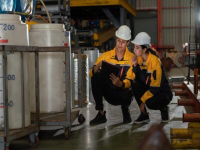
- The intrinsic safety technique is the only technique that allows live maintenance and troubleshooting within the hazardous area without the need to turn the equipment off or use a so called “Hot Work Permit”. This is particularly important for instrumentation, since fault-finding on deenergized equipment is either difficult, or sometimes impossible.
- Intrinsic safety permits the use of conventional instrumentation cables, thus reducing costs. No special mechanical protection of field wiring is required, and ordinary cabling and wiring is acceptable as long as flammable atmosphere transmission to the non-hazardous area is prevented.
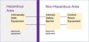
Intrinsically Safe system always consists of:
- Field devices located in hazardous areas (sensing elements, transmitters, contacts, solenoid valves, indicating lights, etc.)
- Associated apparatus – a device typically placed in the non-hazardous area connected by cabling to a field device. Associated apparatus is generally called “IS barrier” and serves a few functions; it monitors and limits energy of the circuits in the hazardous area, provides interface to a control system, and prevents unsafe currents passing from non-hazardous equipment to the field device. IS Barrier operation is based either on energy-limiting and diverting Zener diodes, or on so called “Galvanically Isolating Barriers” that provide complete energy isolation between hazardous and non-hazardous areas (using optical or induction couplers) in addition to energy limiting/diverting.
- Interconnecting cables – Cable capacitance and inductance is often considered a problem. However, this is in fact only a problem on cables longer than 1300 feet, installed in hazardous areas, where NEC Group B (ATEX IIC) gases (hydrogen or similar) could be present.
Misconceptions of Intrinsic Safety
Intrinsic Safety is often something that is misunderstood. Here are some of the misconceptions about the use of Intrinsically Safe Devices that our process safety specialists have come across over the years:
A. Adding an IS Barrier to any kind of electrical device will make it intrinsically safe!
Simply adding an IS Barrier does not make all equipment intrinsically safe. Ignition hazard reduction can only be achieved by installing equipment that has been specifically designed to meet IS requirements along with a suitable IS Barrier. Where intrinsically safe equipment is interconnected by wiring, the safety of each piece of equipment is affected by the performance of the other pieces of apparatus in the circuit. This is a fundamental requirement of intrinsic safety.
B. The safety description of the IS Barrier is compatible with the IS Field Device, is all that is necessary!
Determining IS circuit devices compatibility by checking that the voltage, current, and power outputs of the IS Barrier is less than the voltage, current, and power inputs of the IS Field Device does not guarantee that components selected for IS environments will function effectively. The first step is to ensure that the device is fully compliant (has appropriate certification – listed and labeled according to US NEC definitions) and meets the OEM installation requirements.
C. Zener Barriers and IS Isolators are interchangeable!
There are two types of IS interfaces widely adopted by users of intrinsic safety: IS Zener barriers and IS isolating barriers. These interfaces have very different installation and maintenance requirements, so it is important to understand them.
Most IS Zener barriers are simple, versatile, loop-powered interfaces that require a tightly controlled power source, with limited voltage available in both hazardous and safe area connections. They require a safety earth that is regularly tested as it is a fundamental requirement of the safety of this technique.
IS isolators are more complex and more prone to failure. They are application-specific and can be used with a wide range of power supplies, can provide higher voltage in both hazardous and safe area connections, and simplify regular inspection requirements.
To put it simply – Zener Barriers are simple and reliable but not as effective from the safety standpoint as IS Isolators.
D. It doesn’t matter what cabling/wiring is used if the equipment is IS certified!
Because cables and wires have inductance and capacitance, they have an energy storage capability that can affect system safety. Consequently, the system design imposes restrictions on the value for each of these parameters: but only rarely is there a serious limitation placed on the available cable. This is generally only a concern on installations that may have presence of highly flammable gases such as hydrogen, and interconnection wiring is long.
E. My system is IS. Can I use ordinary conduits and cables without limitations?
Because ordinary cables and conduits can transmit flammable gases and vapors from hazardous to non-hazardous areas, approved conduit seals, or cable glands, or specially designed cables would still be necessary.
Also, it should be remembered that generally, IS wiring and non-IS wiring (including low voltage wiring) must be physically separated by at least 2 inches (50 mm) or by a grounded metal partition – which is necessary to avoid induced voltages and accidental contacts. As a result, generally IS cabling and wiring cannot share the same conduit/wireway with non-IS wiring.
F. Are there Intrinsically Safe Electric Motors? They would make life easier.
Unfortunately, there is no such thing as an Intrinsically Safe electric motor. Conversion of electrical energy into mechanical energy by motors typically requires much higher currents and voltages than IS systems can handle. So, you will have to use a rated motor that provides protection by using one of the other techniques listed in Table 1. Alternatively, if possible, you may consider pneumatically or hydraulicly operated devices.
[1] In general, intrinsically safe apparatus is certified; usually by an independent body such as a NRTL (in US) or Accredited Certification Body (ACB) under the IEC Ex scheme. The exception to the rule is ‘simple apparatus’, which is considered not to affect the intrinsic safety of the system and cannot store/generate energy sufficient for ignitions. This apparatus is exempted from the requirement for certification. The usual examples are dry type contacts, thermocouples, RTD’s and LEDs.

Get in touch
To learn more about our expertise and services in dust explosion prevention & mitigation, call us at +1 609 455 0001 or email us at [email protected] today.
We also offer tailored virtual and in-company process safety training programs on Dust Explosions, Static Electricity and HAC (Hazardous Area Classification) and more. Find further information here.