- Volume Resistivity Test – Powders and Solid Materials
- Surface Resistivity Test – Solid Materials
- Charge Relaxation (Decay) Time – Powders and Solid Materials
- Electrostatic Chargeability Test – Powder
- Breakdown Voltage Test – Solid Materials
- Electrostatic Discharge Testing
- Electrostatic Hazards Testing – Flexible Intermediate Bulk Container (FIBC)
- Liquid Conductivity Test
What are electrostatic tests?
In industry, electrostatic testing is performed on materials being handled/processed (typically powders or liquids) as well as on manufacturing and processing plant in order to assess the hazards posed by static electricity. LABORATORY tests may include powder volume resistivity, liquid conductivity, product chargeability, surface resistivity, resistance, and charge relaxation time (charge decay time). Measurements performed ON SITE may include resistance-to-ground of conductive (metal) items of plant, operators’ footwear, and flooring, and electrostatic voltage/electric field, and charge measurements.
What are electrostatic test results used for?
Electrostatic LABORATORY test results have many critical uses. Electrostatic measurements on powders handled on plant can be used to establish if your materials can give rise to electrostatic hazards by comparing the rate at which static charge is generated with the rate at which it is lost by conduction when in contact with grounded plant. We can also measure powder ‘Minimum Ignition Energy’ to see if your powder can be ignited by a static ‘spark’. Lab measurements on equipment (pipes, liners, big bags….) can be used to explore if such equipment can accumulate static charge – even when it is grounded – and CAUSE electrostatic ignition. Electrostatic measurements ON SITE can be used to check for adequate grounding and bonding of plant and equipment, for testing flooring and footwear in use for electrostatic properties, as well as searching for areas of charge build-up on your plant.
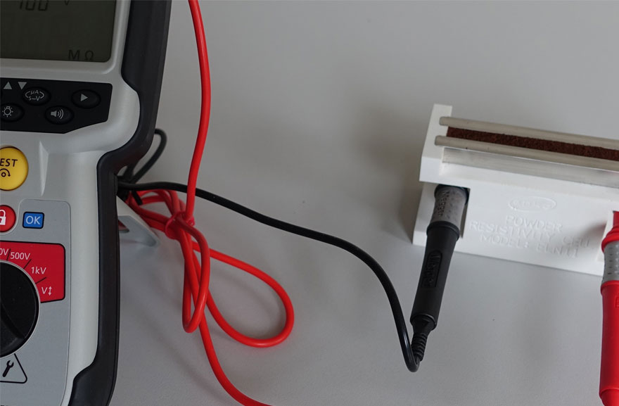
Volume Resistivity Test – Powders and Solid Materials
Volume resistivity is a fundamental property that quantifies how strongly a given material resists the flow of electrical current. A low resistivity indicates a material that readily allows the flow of electric charge. On the other hand, high resistivity (insulating) materials have a propensity to retain electrostatic charge and can produce hazardous electrostatic discharges.
Volume resistivity is a measure of the electrical resistance for a unit volume of material. The SI unit of volume resistivity is ohm.meter (Ω.m). For example, if a 1m × 1m × 1m solid cube of material has metal sheet contacts on two opposite faces, and the resistance between these metal contacts is 1Ω, then the resistivity of the material is 1Ω.m
Volume resistivity = {(Applied Voltage ÷ Measured Current) x (Area of metal contacts ÷ Length between contacts)}
Volume resistivity measurement involves placing the material sample between two metal electrodes that are electrically isolated from each other and electrical earth, applying a DC voltage to one electrode and measuring the current that flows through the material to the other electrode. Volume resistivity is calculated using the known voltage, the measured current, and the geometrical relationship between the electrodes.
The water vapor in air (humidity) can be absorbed/adsorbed onto surfaces and increase the surface and/or volume conductivity. This effect must be taken into account. Testing is therefore typically performed under both low (<10%) and ambient humidity conditions.
Volume resistivity is determined in general accordance with the requirements of the current edition of the American Society for Testing and Materials (ASTM) D257.
Surface Resistivity Test – Solid Materials
Surface resistivity is a measure of the electrical resistance across a unit square surface of material and is a means for classifying materials as conductive, semi-conductive (static dissipative), or insulating.
Surface resistivity is measured by placing – in parallel – two identical rectangular metal electrodes on the test surface such that the distance between the electrodes is equal to the electrode length, applying a DC voltage to one electrode and measuring the current that flows over the material surface to the opposite electrode. Surface resistivity is calculated using the applied voltage, the measured current, and the geometrical relationship between the electrodes.
The water vapor in air (humidity) can be absorbed/adsorbed onto surfaces and can increase surface and/or volume conductivity. This effect must be taken into account. Testing is therefore typically performed under both low (<10%) and ambient humidity conditions.
Surface resistivity is determined in general accordance with the requirements of the current edition of the American Society for Testing and Materials (ASTM) D257.
Charge Relaxation (Decay) Time – Powders and Solid Materials
The rate of electrostatic charge relaxation (charge loss) from a material to earth provides an indication of the relative conductivity (or resistivity) of the material. The electrostatic charge relaxation rate is determined by first charging the test material (typically by corona ionization) and then connecting the charged sample to electrical earth and measuring the electrostatic charge level as a function of time.
The water vapor in air (humidity) can be absorbed/adsorbed onto surfaces and can decrease charge relaxation time. This effect must be taken into account. Testing is therefore typically performed under both low (<10%) and ambient humidity conditions.
Electrostatic Chargeability Test – Powder
Powder particles are expected to become electrostatically charged during handling and processing operations such as pneumatic conveying, pouring, blending, and fluidization. The magnitude and the polarity of the charge is influenced by factors such as the nature of contacting surfaces, particle size (and shape), nature of contact, and velocity of contact and separation.
Electrostatic chargeability of a powder is typically measured by transferring it through a pipe at different transfer speeds and measuring the resulting charge per unit mass.
The water vapor in air (humidity) can be absorbed/adsorbed onto surfaces and affect chargeability. The extent of this influence must be considered by typically conducting the chargeability test at low (<10%) and ambient humidity conditions.
The Powder Chargeability Test is conducted in general accordance with the requirements of the American Society for Testing and Material (ASTM) D4470.
Breakdown Voltage Test – Solid Materials
Breakdown voltage is a characteristic of an insulating material that defines the maximum voltage difference that can be applied across the material before a portion of the insulator breaks down. This breakdown usually forms a weakened path within the material by causing permanent molecular or physical changes along the path of the electric current.
Breakdown voltage can be used as a measure of the tendency of an insulating material to give rise to propagating brush discharges, which can occur in very high electrostatic charging situations. Only materials possessing certain voltage breakdown properties can support the double layer charge needed to produce propagating brush discharges. Propagating brush discharges are highly-energetic discharges capable of igniting many flammable atmospheres.
Breakdown voltage is typically measured by placing the test material on a grounded metal plate and positioning a cylindrical metal electrode that is connected to a high voltage DC power supply on top of the material. The voltage to the electrode is increased until a large current passes through the material to the grounded metal plate.
Breakdown voltage determination can be made in accordance with the requirements of the American Society for Testing and materials (ASTM) D3755.
Electrostatic Discharge Testing
Insulating materials and conductive materials that are isolated from ground can become electrostatically charged and present a static discharge/ spark risk. It is essential that the potential for energetic (incendive) static discharges from all equipment/ component is identified and excluded from locations where flammable/explosible gas, vapor, and/or dust cloud atmospheres may be present.
ESD Test 1: Maximum Spark Energy Assessment – Isolated Conductors
Equipment for use in hazardous flammable explosible areas should, in general, avoid design that causes conductors to be electrically isolated from ground. Sometimes this is not possible, in which case it is essential to ensure the maximum stored electrostatic energy on these components is less than that which can ignite anticipated flammable atmospheres. This Spark Energy Assessment establishes maximum energy through capacitance and voltage measurements and applied calculation methods.
ESD Test 2: Charge Transfer Measurement – Insulators
Brush discharges and Propagating Brush discharges from Insulting (e.g., plastic) equipment/ components can ignite some flammable gas, vapor, and/or dust cloud mixtures. Equipment or components with smaller exposed surface areas are less likely to produce incentive discharges but factors that affect discharge energy are many, and sometimes testing is required. Test samples are electrostatically charged using a variety of contact charging and ionization methods and attempts made to produce electrostatic discharges. Charge transfer measurements allow an assessment of electrostatic discharge energy.
The Direct Discharge Incendivity Test is conducted in accordance with the requirements of IEC/TS 60079-32-1.
ESD Test 3: Direct Discharge Incendivity (Igniting Power) Measurement – Insulators
The incendivity (igniting power) of all discharge types from insulators can be assessed by direct ignition of flammable gas-air mixtures of known Minimum Ignition Energy (MIE). Test materials can be charged by rubbing or by ionization, and discharges drawn from test surfaces to a ‘gas probe’ that attempt to ignite flammable atmospheres of know MIE. Repeated testing allows for an analysis of the incendivity of static discharge.
The Direct Discharge Incendivity Test is conducted in accordance with the requirements of IEC/TS 60079-32-1.
Electrostatic Hazards Testing – Flexible Intermediate Bulk Container (FIBC)
IEC 61340-4-4 (Electrostatic Characteristics of Flexible Intermediate Bulk Container) specifies requirements for FIBCs intended for use in hazardous explosive atmospheres. Hazardous explosive atmospheres may be created by FIBC contents or may exist in the building where the FIBC is being filled or emptied.
There are four FIBC Types: “Type A, “Type B, “Type C, and “Type D that are defined by their construction, nature of their intended operation, and the associated performance requirement.
Type A FIBCs are constructed from insulating fabric or plastic sheet with no provision for controlling any type of electrostatic discharge. Type A FIBCs must not normally be used where a flammable atmosphere with Minimum Ignition Energy ≤1,000mJ is present.
Type B FIBCs are constructed from insulating fabric or plastic sheet designed to prevent “Sparks and “Propagating Brush Discharges. Type B FIBCs are intended for use in dust environments with ignition energies greater than 3mJ. There must be no flammable vapors or gases present.
Type C FIBC design relies on grounding to prevent electrostatic hazards. Type C FIBCs are therefore constructed entirely from conductive material or at least contain fully inter-connected conductive threads or tapes at maximum specified spacings. Type C FIBCs are intended for use in the presence of flammable vapors or gases, or combustible dusts with MIE ≤3mJ.
Type D FIBCs are constructed from fabrics with special static protective threads and/or properties to control discharge incendivity without earthing. Type D FIBCs are intended for use in the presence of flammable vapors or gases, or combustible dusts with MIE ≤3mJ.
FIBC Testing Requirements
For all types of FIBCs:
- Minimum Ignition Energy (MIE) of the powder. If MIE less than 25mJ, then
- Electrostatic Volume Resistivity of the powder
- Electrostatic Chargeability of the powder
- Minimum Ignition Energy of flammable gas or vapor atmosphere, if present
Type B FIBCs:
- Electrical Breakdown Voltage of the fabric and liner
Type C FIBCs:
- Electrical Resistance between the grounding strap and any conductive location on the FIBC surface
Type D FIBCs:
- Incendivity of Electrostatic Discharges from the surface of the FIBC during full-scale filling and emptying operations according to the specifications of IEC 61340-4-4 (Electrostatic Characteristics of Flexible Intermediate Bulk Container)
Liners for use in FIBCs
- Surface Resistivity
- Electrical Breakdown Voltage
Liquid Conductivity Test
Conductivity is used to classify liquids as low, medium, or high conductivity. Low conductivity liquids are susceptible to electrostatic charge generation and retention and can give rise to hazardous electrostatic discharges.
Liquid conductivity measurement involves placing the liquid sample between two metal electrodes that are electrically isolated from each other and electrical earth, applying a DC voltage to one electrode and measuring the current that flows through the liquid to the other electrode. Liquid conductivity is calculated using the known voltage, the measured current, and the geometrical relationship between the electrodes.
The Liquid Conductivity Test is performed in accordance with the requirements of American Society for Testing and Materials (ASTM) D4308.